
Product Design of a 4 wheel differential drive robot
09 Jan 2019I have been thinking of creating a small mobile robot from scratch. From scratch means, go through all the steps of a product development. Design the overall architecture, design the circuits, make 3D model of the parts, 3D print the parts and finally integrate with ROS.
The methods I followed may not be the best practice. The only aim is to reach from idea to actual product (prototype).
Features
- 4 Wheel Differential Drive
- Camera
- WiFi
- IMU
- GPS(optional)
Overview
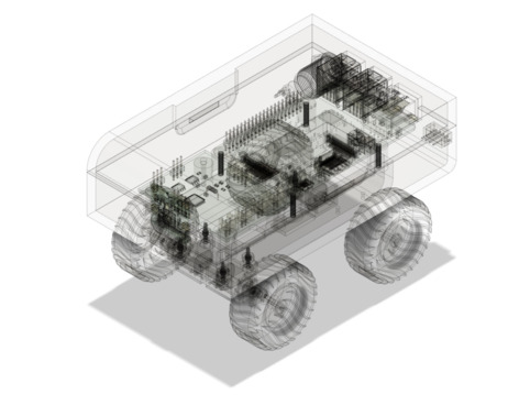
A 4 wheeled differential mobile robot with wheel encoders, camera, WiFi, IMU and GPS(optional). The first thing I did was to come up with an overall architecture. Raspberry pi 3 will be the heart of the robot. Pi Zero was considered in the beginning, but eventually had to change because of the lack of support for ROS. Even though able to compile ROS from scratch, it became so hard to compile other packages needed for the project. Since I do not want to use pi to directly control motors, I had to design a separate controller circuit to handle motors. Encoder was later discarded to make the project simple. Controller circuit will talk with pi using i2c. Atmega328p is used for the controller circuit. IMU will also communicate with pi using i2c.
Architecture
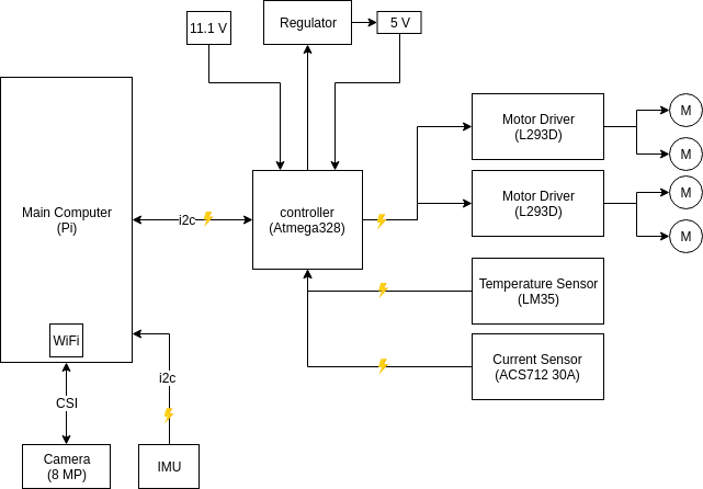
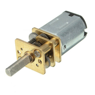
Selected N20 DC12V 300RPM motor for driving the robot. With a rated torque of 0.4 Kg/cm, it was more than enough to drive the robot since expected overall weight of robot will not cross 1 Kg. Selected a battery with voltage 11.1 which is enough for the motors. A voltage regulator is needed to power Pi and motor circuits. Atmega328P is selected for the controller circuit. It has enough internal PWM to drive 4 motors. Since I had to make the controller circuit as small as possible, I was searching for SMD components. Found one SMD package for l293D which is enough to drive the motor with a stall current 300 mA. In order to keep track of current, I selected ACS712. For measuring internal temperature, LM35 was selected.
Specifications
Motor
Name: N20 DC12V 300RPM Mini Metal Gear Motor (12GAN20)
shop: banggood
| Rated voltage | DC 12V |
| Speed | 300 RPM |
| Shaft Diameter | 3mm |
| Diameter | 12mm |
| fuselage without shaft length | 26mm |
| Output axial length | 10mm |
| Screw | M3 |
| Quantity | 4pcs |
| Non-loaded | Non-loaded | Rated load | Rated load | Rated load | stall | stall | ||
| Voltage range (V) | Rated voltage | speed(RPM) | current(A) | speed(RPM) | current(A) | torque(KG.CM) | torque(KG.CM) | current(A) |
| 6-12 | 12 | 300 | 0.05 | 240 | 0.09 | 0.6 | 4.00 | 0.3 |
Main computer
Name: Raspberry Pi 3 Model B+
| Processor | Broadcom BCM2837B0, Cortex-A53 64-bit SoC @ 1.4GHz 1GB |
| Memory | LPDDR2 SDRAM |
| Connectivity | 2.4GHz and 5GHz IEEE 802.11.b/g/n/ac wireless LAN, Bluetooth 4.2, BLE Gigabit Ethernet over USB 2.0 (maximum throughput 300Mbps) |
| Access | 4 × USB 2.0 ports Extended 40-pin GPIO header |
| Video & sound | 1 × full size HDMI MIPI DSI display port MIPI CSI camera port 4 pole stereo output and composite video port H.264, MPEG-4 decode (1080p30); H.264 encode (1080p30); OpenGL ES 1.1, 2.0 graphics |
| Multimedia: SD card support | Micro SD format for loading operating system and data storage 5V/2.5A DC via micro USB connector 5V DC via GPIO header Power over Ethernet (PoE)–enabled (requires separate PoE HAT) |
| Operating temperature | 0–50°C |
| Production lifetime | The Raspberry Pi 3 Model B+ will remain in production until at least January 2023 |
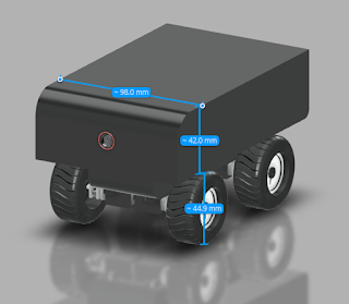
Dimension

Schematics: Link
OS: Ubuntu MATE 16.04.2 (Xenial)
Installation steps: Link
Temperature sensor
- Name: LM35
- Linear + 10-mV/°C Scale Factor
- 0.5°C Ensured Accuracy (at 25°C)
- Rated for Full −55°C to 150°C Range
- Operates From 4 V to 30 V
- Less Than 60-μA Current Drain
- Low-Impedance Output, 0.1 Ω for 1-mA Load
Current sensor
- Name: ACS712ELCTR-05B-T
- Small footprint, low-profile SOIC8 package
- 1.2 mΩ internal conductor resistance
- 2.1 kVRMS minimum isolation voltage from pins 1-4 to pins 5-8
- 5.0 V, single supply operation
- 66 to 185 mV/A output sensitivity
- Optimized current range : ±5
- Sensitivity: 185 mV/A
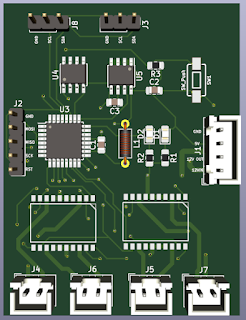
Schematics

PCB Layout
After finishing with the schematics and some initial breadboard prototyping, moved directly to pcb layout design.
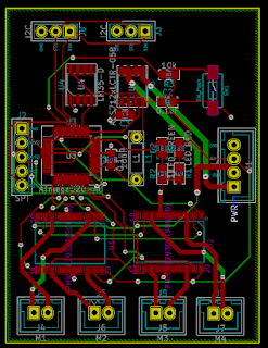

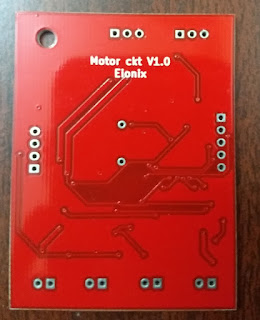
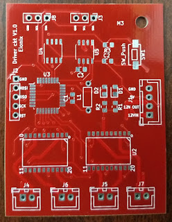
Since it is a 2 layer PCB, I had to order PCB from outside. LION circuits seemed to be a good choice. Apart from the fact that choosing colour of the PCB will cost you double, service seems to be good.
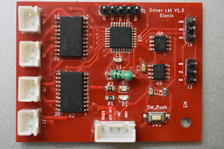
After an hour of hand soldering….
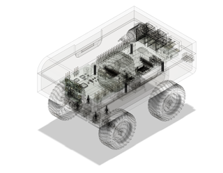
CAD Modelling
I have used solidworks before. But for this project I tried fusion 360, which seems to be good. One weeks of YouTube tutorials was enough to get started. Had to redesign the model two times. But it was worth the effort.

3D printing
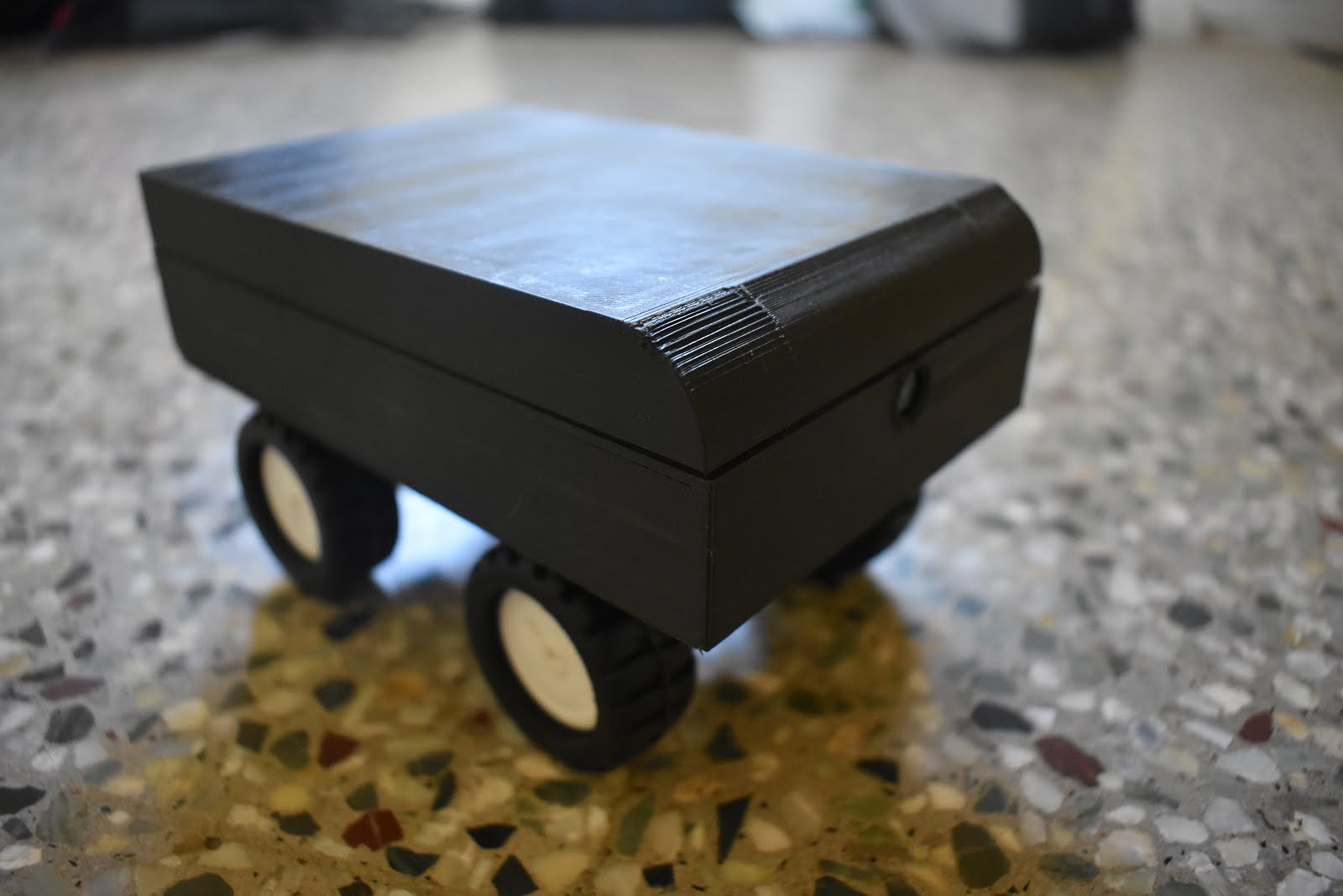
I had two split the bottom body into two parts for easy 3D printing and later I glued it together.
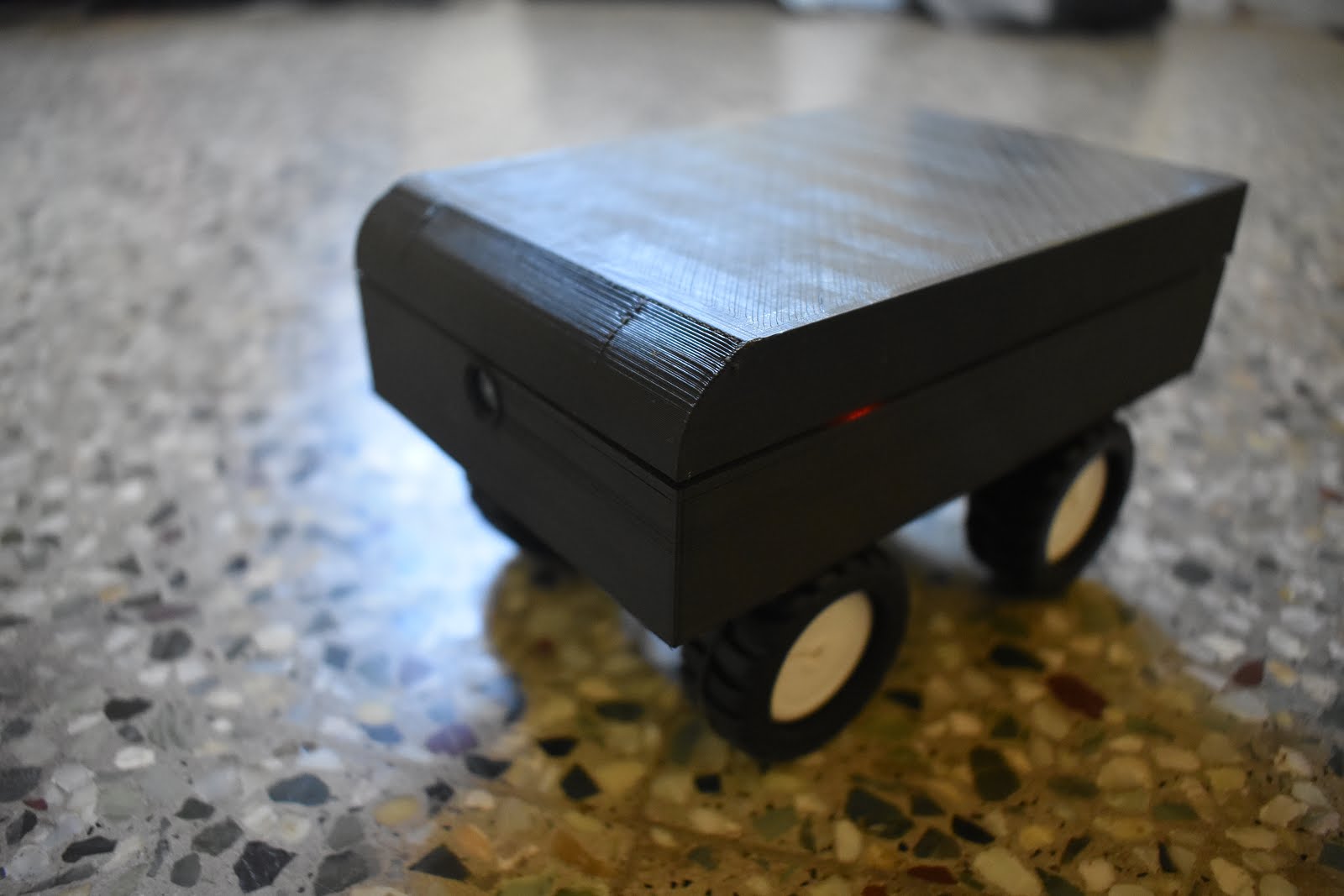
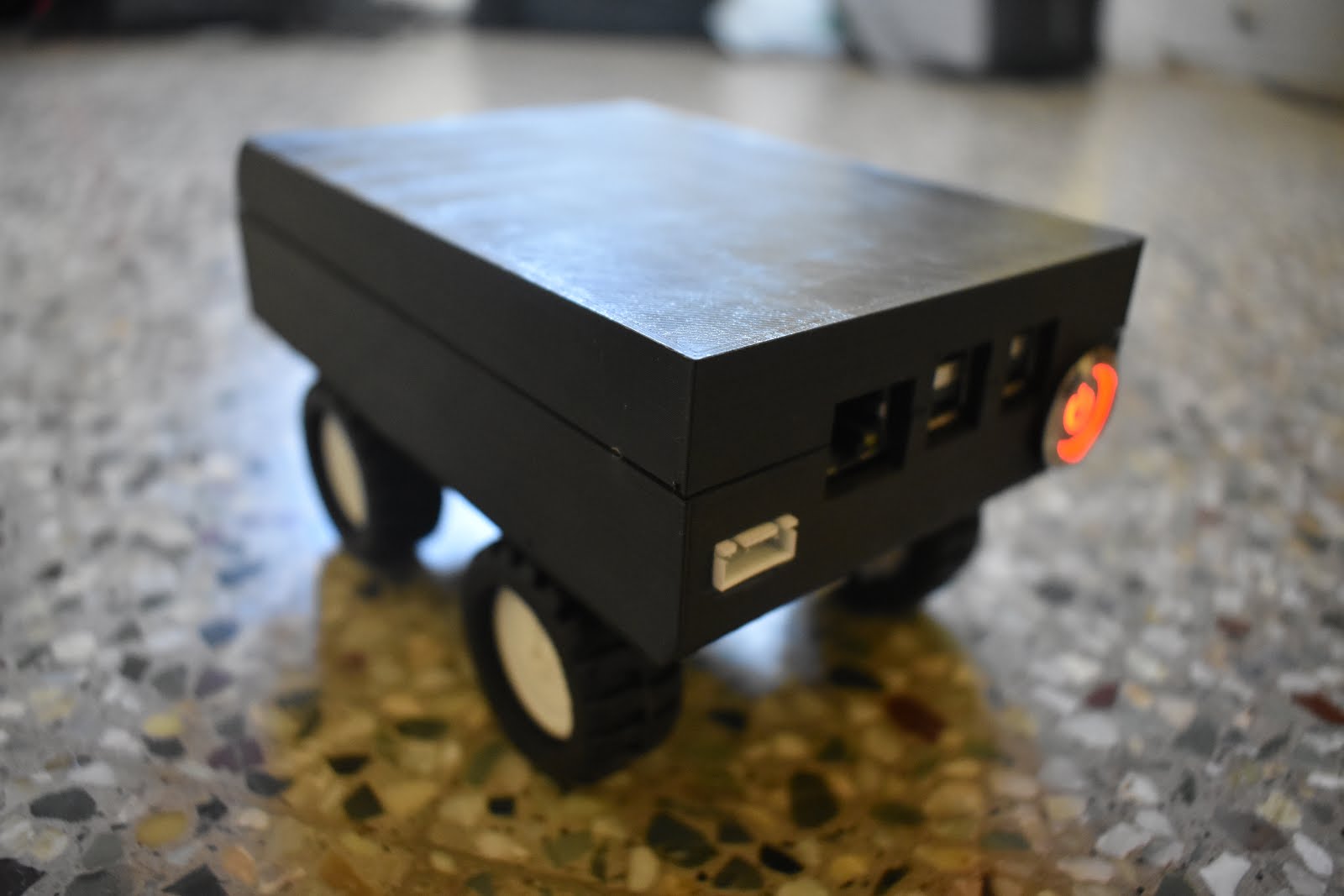
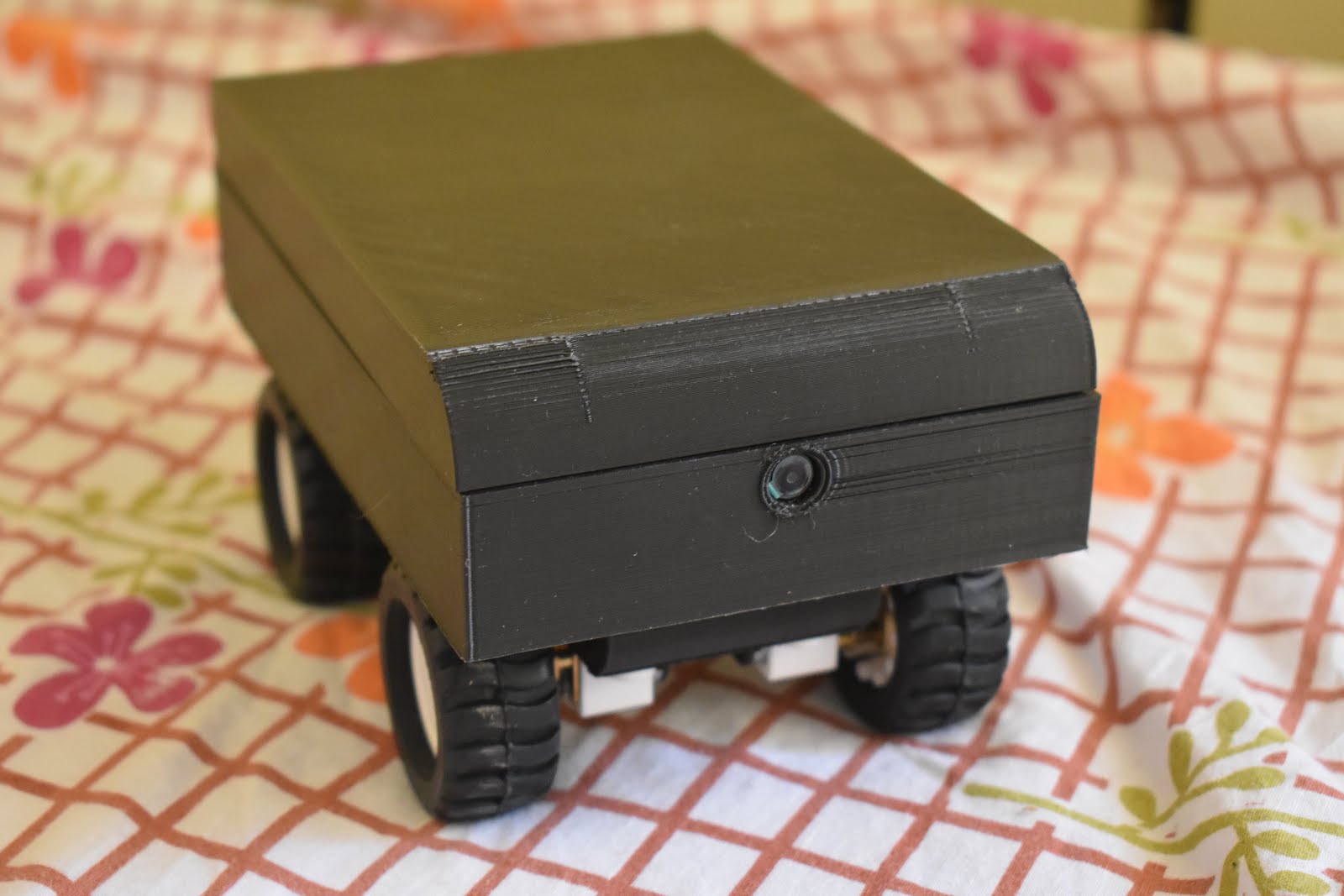
Final Preview